I constantly found my self having to set origin to [0.5,0.5] in Famous Engine, as most of the time I’d want to rotate/scale around the center of an item, which is usually the intuitive thing to do I think. As for aligning, I think starting in the top left is just the same as starting in the center or bottom right, so the default [0,0] is fine in that case. As for mountPoint, I think top left is also fine, so how about the following defaults (I’m iffy on the z-axis parts, I think I’ll get more of a feel for that when I get to WebGL)?
align: [0, 0, 1] (top left front)
origin: [0.5, 0.5, 0.5] (center)
mountPoint: [0, 0, 1] (top left front)
(0.5 on the z-axis for a DOM element has no meaning, but does have meaning for 3D objects)
What do you think about the align and mountPoint z-axis values? Should they be front, middle, or back? For UIs with flat surfaces (DOM elements for example) it might not matter. It will be more for when considering 3D space. Do we start with the front of a 3D space at the viewport (1 on the align z-axis), with the middle (0.5), or with back (0)? And then, when moving an item inside a 3D space, should it’s z-axis mountPoint be 0, 1, or 0.5 (depending on which default align we chose)?
Thanks for the feedback! That’s still a default. x] What would be your expectation when you place something into the scene with defaults, then rotate it? Do you expect the object (imagine a cube) to rotate about its center point, or around one of its corners?
Before I start my opinions, let me say this is definitely something that should be addressed.
This has always been a pain point. Even for those of us that have a grasp on the whole concept. Defining these alignment definitions is key, but understanding these definitions is not easy for a developer new to the library. I myself have to admit that early on I spent hours frustrating myself by going back and forth with layout using the old library.
align = where you put this objects origin with respect to the parent’s (bounding box) size
origin = this objects placement point
mountPoint = the changing of the mount point of an object with respect to it’s own alignment and origin location
ASSUMING the definitions are correct above, we can get confused as a developer quickly for layout. Then add rotating, scaling and sizing, we start to get a headache quickly. Further add the requirement that there is an order of defining these values that is required makes the library a pain to use.
Statement: I do not want to even think about this in my use of a library most of the time, so it should be simpler for the normal user. In most real world cases you will not have a requirement for changing the default values. Start your node definitions and layout and everything will fall in place (overstated maybe). Components would be used to do the heavy lifting and have an easy to understand API.
Conclusion:
No matter what the defaults are there will be someone who will want them different
Most use cases will be top-left-flat [0, 0, 0] for origin and center-flat for [0.5, 0.5, 0] align
z-axis will be applied only for layered layout components typically, so applied as needed
3D layouts will be different on each application
Make the defaults easier to set (API) with maybe a way to easily define defaults (override)
Clearly document the use of advanced features with working examples
I’m not 100% sure about “defaults”, but I expect a few things from an applied perspective:
if I multiply all the matrices along a node’s parent chain that the resulting matrix (c) contains all the transformations applied to that node.
I would like (c) [which is calculated from the scene graph] to match the CSS matrix3d(…)
if I want to rotate around a particular origin, I would a) translate to that rotational origin then b) rotate around that origin.
I don’t want some phantom participant (d) to implicitly add (a) nor do I want any subsequent de-translate of (a) to be implicitly added to the composition of (c).
If you have to have (d) then at least make it explicitly obvious what is going on and in which order.
My philosophical view is that I’m not smart enough to invent some new approach to scene graphs and coordinate systems and that the existing body of knowledge on it is mature [see (1)]. Thus I recommend that you do away with storing position/rotation/etc in the core explicitly, do away with setOrigin/setAlign and replace them all with a 4x4 matrix at each node which defaults to an identity matrix.
If you then want to make the API more accessible to less sophisticated users, mixin a mini framework to implement those implicit align/origin/etc transformations.
I have seen the approach from (1) taught in 3D programming courses at both the Stanford CS school and at RMIT University here in Australia and found myself able to do considerably more in less time with much harder programming environments.
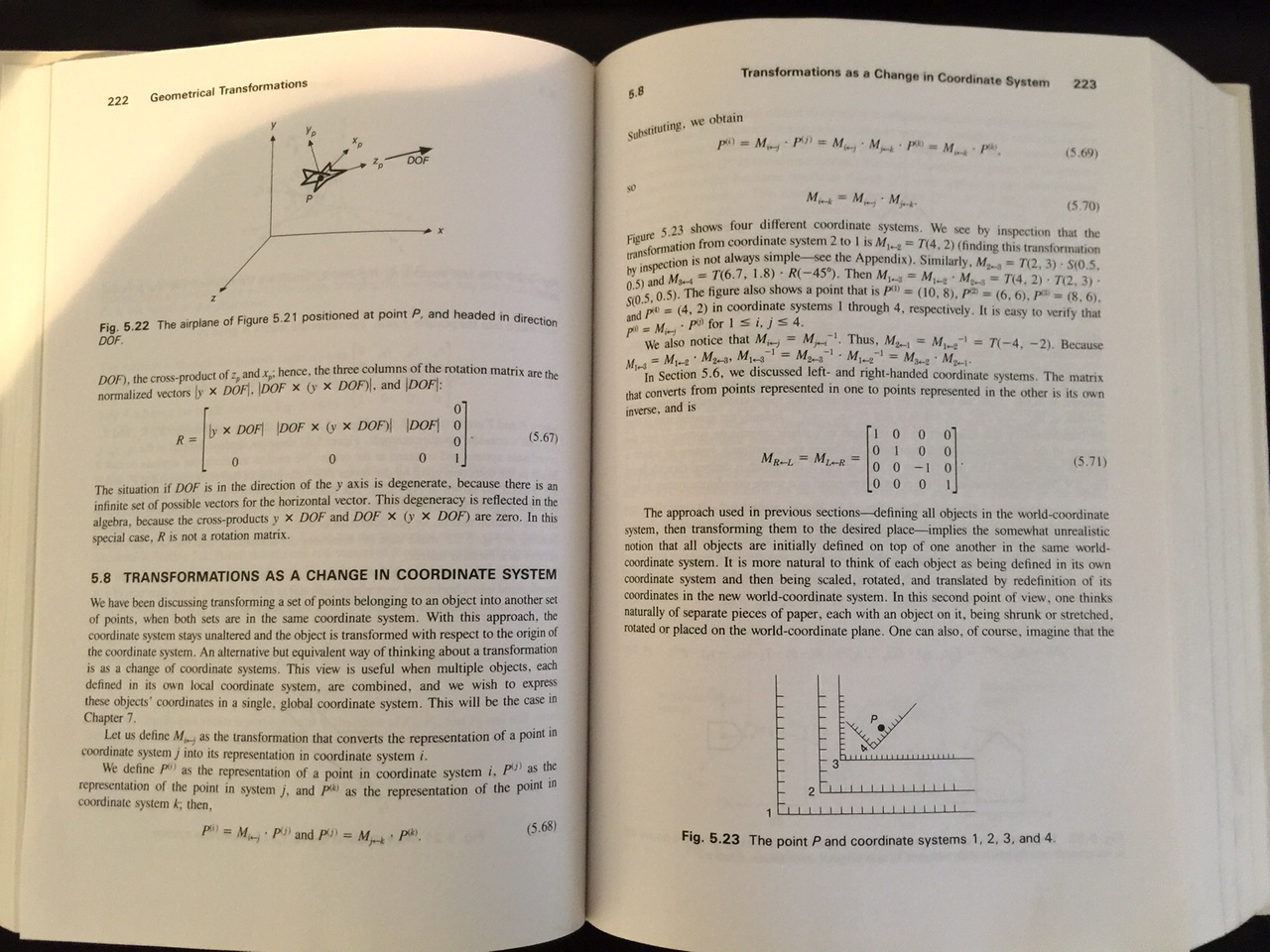
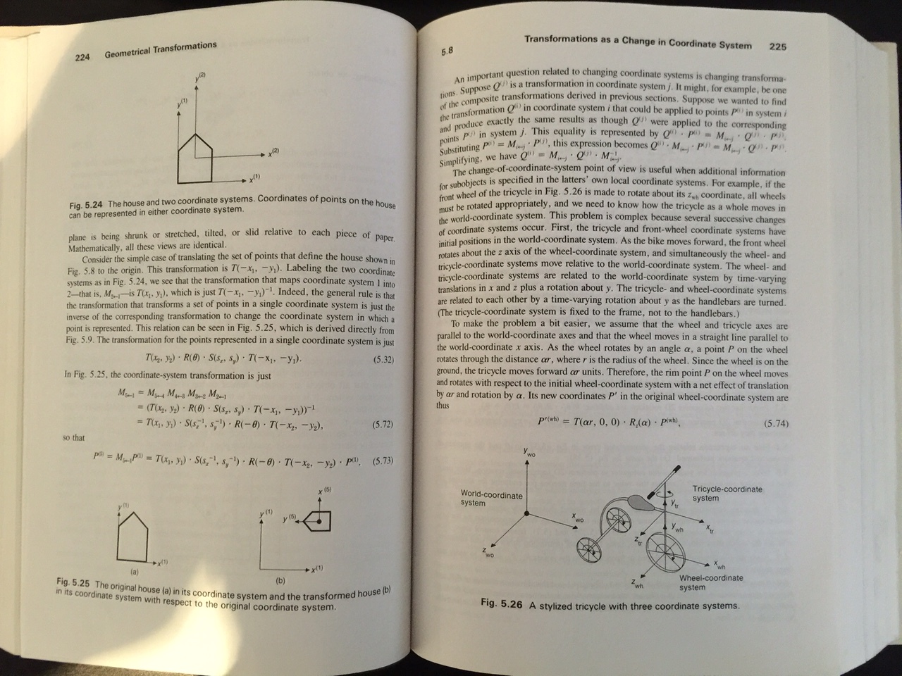
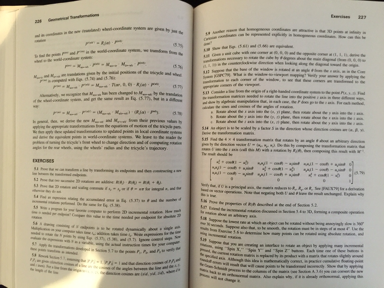
I have uploaded here a few pages from (1), I’ll try and find my old lecture notes on it as well.
(1) Foley, James D., and James D. Foley. “5.3 Composition of 2d Transformations through 5.8 Transformations as a Change in Coordinate System.” Computer Graphics: Principles and Practice. 2nd ed. Reading, MA: Addison-Wesley, 1990. 209-26. Print.
I think the distinction between what has been done in Famous and what I am promoting is that node position shouldn’t be described in terms of a single point but rather as a composition of transformations to a set of points. This is a more robust concept because a node can occupy >> 1 point in the 3d space. Do away with that single point concept and things become much simpler.
The purpose of the core of your framework should then be to introduce the abstract concept of volume in 3-space because this doesn’t exist in the DOM but is required for 3D programming.
Or is changing the way in which coordinates are represented also a purpose of the framework?
This is a highly theoretical question and one worth debating!
(4) Angel, Edward. “10.2 Hierarchical Models through 10.5 Use of Tree Data Structures” Interactive Computer Graphics: A Top-down Approach with OpenGL. Reading, MA: Addison-Wesley, 2000. 499-513. Print.
(5) Möller, Tomas, and Eric Haines. “9.1 Spatial Data Structures.” Real-time Rendering. Natick, MA: AK Peters, 2002. 346-57. Print.
NB. The lecture notes from RMIT are similar to (2) and (4). The Stanford notes leave it as background reading and focus on using the data structure for things such as scan-lines, rasterizing, compositing, collision detection, culling & texture position.
I’m just a simple aerospace engineer, but I find frames of reference to be a useful concept that seems to be poorly taught in computer science. It think it might be applicable here, as it is how i’ve always understood 2D and 3D computer graphics.
The cognitive leap is to forget about the object you are trying to place and think in terms of translating and rotating spaces. The idea is to construct a chain of transforms that creates a space where the object can be permanently placed at the origin in a more-or-less standard orientation. Each transformation is done with a generalized coordinate (usually a distance or an angle) that has a name and becomes a parameter. That’s how we engineers make sense of aircraft and spacecraft dynamics.
So my observation is that we are trying to do too much with each node. I propose that we define several kinds of nodes that each represent a single affine transformation - rotate (about the origin), translate, scale (again, about the origin), and if we need it, skew - with a single scalar variable denoting the generalized coordinate. The order of changing of the nodes defines the order of operations on the transform matrices.
So yeah, this means a bunch of extra classes and bigger graphs, but the graph will be easier to understand and debug.
So, for example, to put an object in the center of a [400, 500, 200] view space with origin in the upper left front corner:
A = TranslateNode( [4, 5, 2] ); // [4, 5, 2] is the translation vector in the view frame that positions space A
B = RotateNode( [0, 0, 1]); // [ 0, 0, 1] is the vector in space A that the rotating space B rotates about
C = TranslateNode( [-50, -50, 0 ] ); // [-50, -50, 0] is the vector in space B that pushes the mounting frame C to center the space
D = Surface( [100, 100] ); // D is a [100.100] rectangle with upper left corner at the origin of space C.
A.setValue(50); // Slides frame A [200, 250, 100] from the origin of the root space
Then you put B in a loop with increasing setValue calls to spin frame B.
Anyhow, this is how I think of things. I have no idea if it follows the graphics conventions for computer science. Obviously we want to do that as closely as possible to lower the learning curve for graphics professionals.
The approach I present differs from the matrix approach by using vectors instead of matrices in the API and a single mutable scalar as the sole parameter. I think this might be easier for people to grasp than matrices. Internally the functionally is exactly the same.
One can have the same interface you are proposing and still have a matrix representation internally. From an application perspective, your interface is exactly the sort of thing I would like to see.
Right now its not possible to do such a thing with Famous and I’m hoping that Motor/Infamous doesn’t make the same mistake.
Yes, clearly. Internally a matrix approach is the way to go. Kane’s method in Dynamics offers a pretty mature notation for thinking about chained reference frames. If you haven’t read his book I highly recommend it.
I’ve had this idea for a while now too! This will only apply to WebGL though, as we can’t bend DOM elements, so having a single point makes with DOM. But, with WebGL, what I’ve been imagining letting Nodes of a scene graph have the ability to hold a vertex (not just a whole Mesh like Famous 0.5+). So, suppose we want to animate the vertices of a WebGL cube. We could create 8 Nodes, create 8 Vertex instances, attach the vertices in the order needed to create the 6 sides of a cube, then position the Nodes in space in order to create a cube, but we can also position the Nodes in other ways to create other shapes besides a Cube. We could easily make a wobbly cube by animating each Node (and hence each Vertex). I will for sure implement this idea eventually, once I’m in the WebGL phase of my prototype. There’s lots to do before that though, like mesh cutting in order to blend DOM with WebGL, and animating vertices will make that more complicated, but definitely doable.
As for volume, my prototype is already design with 3D in mind, in every axis. For example, even though right now I’m only rendering DOM, every Node has position, rotation, align, size, etc, in all 3 axes by default (size is just defaulted to zero for DOM elements, etc). If size in the 3rd axis is not zero, and align is 0.5 in all axes of a parent Node, then the child will be anchored in the middle of that 3D space, even if it is a 2D DOM element.
I’m not sure what you mean by “changing”, but in my prototype the coordinate system starts at the top left, to be easy to understand from a traditional HTML developer’s perspective. Famous did the same thing too. However, maybe we can give Nodes an API so that the direction of each axis can be modified. For example, in traditional HTML, positive translation goes down and to the right, but in some other (game) engines positive translation goes up and to the right (with origin at the bottom left instead of top left). It might be nice to make this configurable for the developer who wishes to configure it. In any case, as you might already know, it’s not hard to make a transformation matrix that converts from one coordinate system to the other, and that can be applied to the root scene even if no such direction-swapping API exists.
This can already be done in Famous and in in any of our prototypes without the need for extra classes. Just simply chain the Nodes in the order that you wish, and apply only those values that you need to each Node (rotation, scale, etc). Nodes in my prototype use DOMMatrix for their affine transforms (natively in Firefox, or via my polyfill of the Geometry Interfaces spec in browsers that don’t have support yet). The order that the nodes are in the scene graph will determine the order in which the transforms are applied.
Your example would be more like this using my prototype (so far):
var translateNodeA = new Node().translate = translateOnVector([4,5,2], 50)
var rotateNodeB = new Node().rotate = rotateOnAxis([0, 0, 1], 0)
var translateNodeC = new Node().translate = ...
var surfaceNode = new Node().size = [100,100,0]

// Nodes have a DOM element by default, for now:
console.log(surfaceNode.element)

root.addChild(translateNodeA)
translateNodeA.addChild(rotateNodeB)
rotateNodeB.addChild(translateNodeC)
translateNodeC.addChild(surfaceNode)

// a simple rotation animation:
let rotation = 0
requestAnimationFrame(function loop() {
  rotateNodeB.rotate = rotateOnAxis([0, 0, 1], rotation++)
  requestAnimationFrame(loop)
})
where translateOnVector, is a helper function to translate about a specific vector/axis, otherwise the .translate property in the example accepts [x,y,z] translation values directly (similar with the rotation helper).
You can also use a single Node (which would be more performant) and use the DOMMatrix API to perform matrix calculations in the order that you wish.
I think I’d rather make it easy to translate about a vector, etc, with helpers/methods, but encourage a Node to have a single affine transformation matrix for those who wish to manipulate matrices directly. The docs could show how to do specific things like what you want (sequences of operations using matrix multiplication and/or chained Nodes), and helpers/methods can make those things easier to do. It is also possible that the order that rotation, translation, etc, is applied to a single Node would matter, which would help your use case. For example,
node.rotate = ...
node.translate = ...
could possibly have a different result than
node.translate = ...
node.rotate = ...
but it might be better to encourage Node chaining or manual matrix multiplication for this purpose, so that the Node API doesn’t lead to confusion for new users when they’ve set values in different orders and have gotten different results.
An idea: we could add classes built on top of DOMMatrix that represent matrices for specific things, for example: RotationMatrix, PositionMatrix, ScaleMatrix, etc. We could then multiply those matrices in any order.
We can already do that with Famous 0.5+: just chain the Nodes, then apply individual Size, Rotation, Position, etc, components. We’ll definitely still be able to do this in infamous/motor.
Thanks for the input guys. I’ll keep it all in mind with my prototype, and I’ll let you know when some examples are up, then you can let me know what you think. I’ll specifically create an example like the above chained-Node example. :}
Yes, internally it should collapse down to something like this. This collapse could be done with a compiler if the grammar is simple enough. Having separate classes.would make the parsing simpler. However, this performance tweaking can wait until a much later version. IMHO, it’s much easy enough to performance tune behind a stable interface than it is to break the API to make the tuning possible. The community doesn’t need to be involved in the former but will loudly weigh in on the latter.
The order of matrix operations has a very definite effect on the final position. I’m an aerospace engineer by trade, and in my experience the order of application for frame transformations is the most fundamental sources of error in 3D systems. I’ll use the example my flight dynamics teacher used as the example:
Find an object that could be used to represent an aircraft - a pair of scissors will do if you don’t have a model aircraft handy, or just use your hand. In aerospace, the X axis points out the nose of the aircraft, the Y axis points out the right wing, and the Z axis points down.
The “standard” way us aerospace engineers look dorky at our desks is to wave our right hands around as stand-ins for the orthogonal body-fixed coordinate system of a vehicle. When we do this our thumbs always point forward as the X axis, index fingers point out the right wing as the Y axis, and middle finger points down as the Z axis. In aerospace terminology, pitch is a clockwise rotation about the Y axis (index finger), yaw is a clockwise rotation about the Z axis (middle finger), and roll is a clockwise rotation about the X axis (thumb)
So experiment a bit. With your right hand rigid in this configuration point your index finger forward, your thumb to the left, and middle finger down. The “aircraft” is flying right to left in front of your body. Now apply a few rotations. First do pitch-roll-yaw; apply a pitch value of 90 degrees (rotate about index finger until thumb points up), a roll value of 90 degrees (rotate about your thumb until your index finger points right), and a yaw value of 90 degrees (rotate about your middle finger until your index finger points down. Your thumb should be pointed to the right, your middle finger forward, and your index finger down.
Now do it backwards with yaw-roll-pitch. Yaw points index finger to the right, roll points index finger down, and pitch points your thumb to the right. So far so good, your hand is in the same orientation.
Now try roll-pitch-yaw. Roll points the index finger down, pitch points the thumb forward, and yaw tries to break your wrist to get your thumb pointing down. If you’ve got rubber wrists your index finger is now pointing at your body, your thumb is pointing down, and your middle finger is pointed to the left. Throwing a few translations in just makes it worse.
I spent a lot of time digging through the internals of Famous trying to find why the order of operations I specified was altered by the rendering process. Part of the problem seemed to be due to trying to use DOM conventions to do something the DOM was never designed to do. The rest I never quite figured out. Cubes and other structures that I built would work fine on one browser but grenade themselves on another.
I had this problem. I’m not sure why it was, but I believe that the nested DOM strategy solves this in all browsers now (Edge has it now, IE 11 didn’t). The DOM generated by Famous 0.3 was not nested, but then Famous 0.5+ started using the nested approach. I theory, both approaches should work fine now, in all browsers (minus the performance differences where Chrome drastically wins). This three.js periodic table is using the non-nested approach, and besides being really slow in Firefox, it renders essentially the same in both Chrome and FF. It could be there was a bug in Famous too, but I never looked into it since I was deving in Chrome and didn’t really care about the other browsers in my case.